Chlorine Dioxide and its various applications in Oilfield Operations
Abstract
Chlorine dioxide has a wide variety of applications in the oilfield, including fracturing, water flood, salt water disposal wells and producing well stimulation. It is uniquely suited to deal with the core problems of microbiological fouling, H2S, iron sulfide and oil/water emulsions. The unique attributes of this oxidizing chemical mean that it will not react with hydrocarbons and most amines (unlike other oxidizers), and thus is effectively targeted on the problems most commonly encountered.
There are multiple ways to generate chlorine dioxide, both from the standpoint of the precursor chemicals used, and the equipment used for the generation. This paper will address these methods of generation and application of chlorine dioxide, along with the advantages and disadvantages of each for specific types of application.
Why Chlorine Dioxide?
Virtually all oilfield systems contain and/or utilize water. This may be in the form of fresh water used for fracturing operations or produced water used for anything from fracturing to water flood or disposal. Any aqueous oilfield environment inevitably results in several ubiquitous problems.
- Bacteria will be present, both aerobic and anaerobic varieties. These bacteria result in:
-
- Formation of biomass that will
-
-
- Form rag layers in gathering tanks,
- Foul piping, well bores and formations
- Cause differential cell corrosion on metal surfaces
- Form emulsions with hydrocarbons
- Anaerobic sulfate reducing species will produce H2S, which is both
- Highly toxic, and
- Corrosive
-
- H2S corrosion of piping systems and formation iron results in large amounts of iron sulfide (FeS) in both the water and hydrocarbon phase
- FeS stabilizes oil/water emulsions, producing additional fouling
The total effect of bacterial growth on oilfield systems is generally substantially underestimated by producers. However, if it is controlled and the downstream effects (H2S and FeS formation) prevented, most production limiting issues can be largely eliminated. While efforts have been made to address individual issues in recent years (various nonoxidizing biocides for bacterial control; H2S scavengers, etc.), none have been completely successful.
Over the last five to seven years, however, chlorine dioxide (ClO2) chemistry has proven to be extremely effective at targeting all these issues. As an oxidizing chemistry, it will rapidly provide bacterial kill (unlike nonoxidizing biocides) when fed to obtain a small residual.1 It also destroys H2S, which vastly improves personnel safety and resolves most corrosion issues. In addition, by eliminating FeS, it rapidly resolves most emulsions, which are typically stabilized by the presence of the FeS. Finally, being a relatively weak oxidizer, it will not react with most hydrocarbons — resulting in much lower dosages than other oxidizing chemistries and none of the objectionable reaction byproducts those others form with hydrocarbons.
Chlorine dioxide is, thus, an almost perfectly targeted chemistry for resolving a great many vexing oilfield problems.
Uses and Application Methods of Chlorine Dioxide in the Oilfield
As previously mentioned, probably most long-term operational problems in oilfield operation result from bacterial growth. Not only do the bacteria form biomass (bacteria within slimy exopolymers) that directly foul tanks, form rag layers, plug formations downhole, etc., but they result in the formation of H2S and FeS due to H2S corrosion of iron/steel in the systems.
So, most applications center around accomplishing the following goals:
- Killing bacterian
- Eliminating H2S
- Eliminating FeS
- Destroying biomass and emulsions that result from bacteria and FeS
The next question that arises is — “By what process does ClO2 accomplish these goals?” So, a brief discussion of how the chemistry works is in order.
Bacterial Kill / Biomass
Chlorine dioxide has several advantages over other biocides under these conditions. A summary of its advantages is presented here, but for a more thorough discussion two books by Dr. Greg Simpson are highly recommended: Practical Chlorine Dioxide Volume 1 — Foundations, and Practical Chlorine Dioxide Volume 2 — Applications.
- ClO2 rapidly kills all microorganisms at lower dosages than other biocides and maintains a residual for downstream disinfection and biofilm mitigation.
- It is rated as a “green” chemistry, ultimately decaying to salt.
- Does not react with hydrocarbons in the water, thus offering much lower dosage requirements than other oxidizing chemistries.
- A neutral charge molecule that easily penetrates biomass to kill.
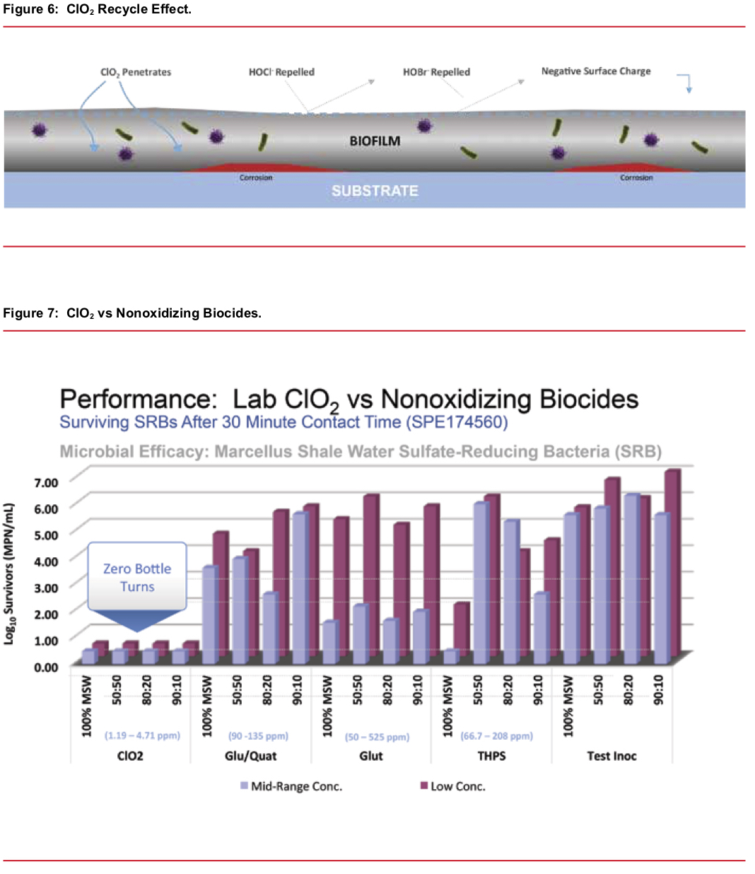
- A “recycle” feature — when ClO2 reacts with the bacteria/biomass the majority reverts to chlorite ion. Acid from acid producing anaerobic bacteria species reacts with the chlorite and forms additional ClO2. Thus, a high level of ClO2 is regenerated inside the biomass and results in a rapid and complete kill and dissolution of the biomass. See Figure 6
One crucial factor favoring chlorine dioxide over nonoxidizing biocides is that you can directly measure a residual concentration. Given the way it works (physical oxidation/destruction of key cellular components) bacteria will be killed when there is a measurable unconsumed residual amount of ClO2 present. This is not true of nonoxidizing biocides. The relative effectiveness of ClO2 compared to nonoxidizing biocides is illustrated in Figure 7.
H2S/Sulfide Reactions
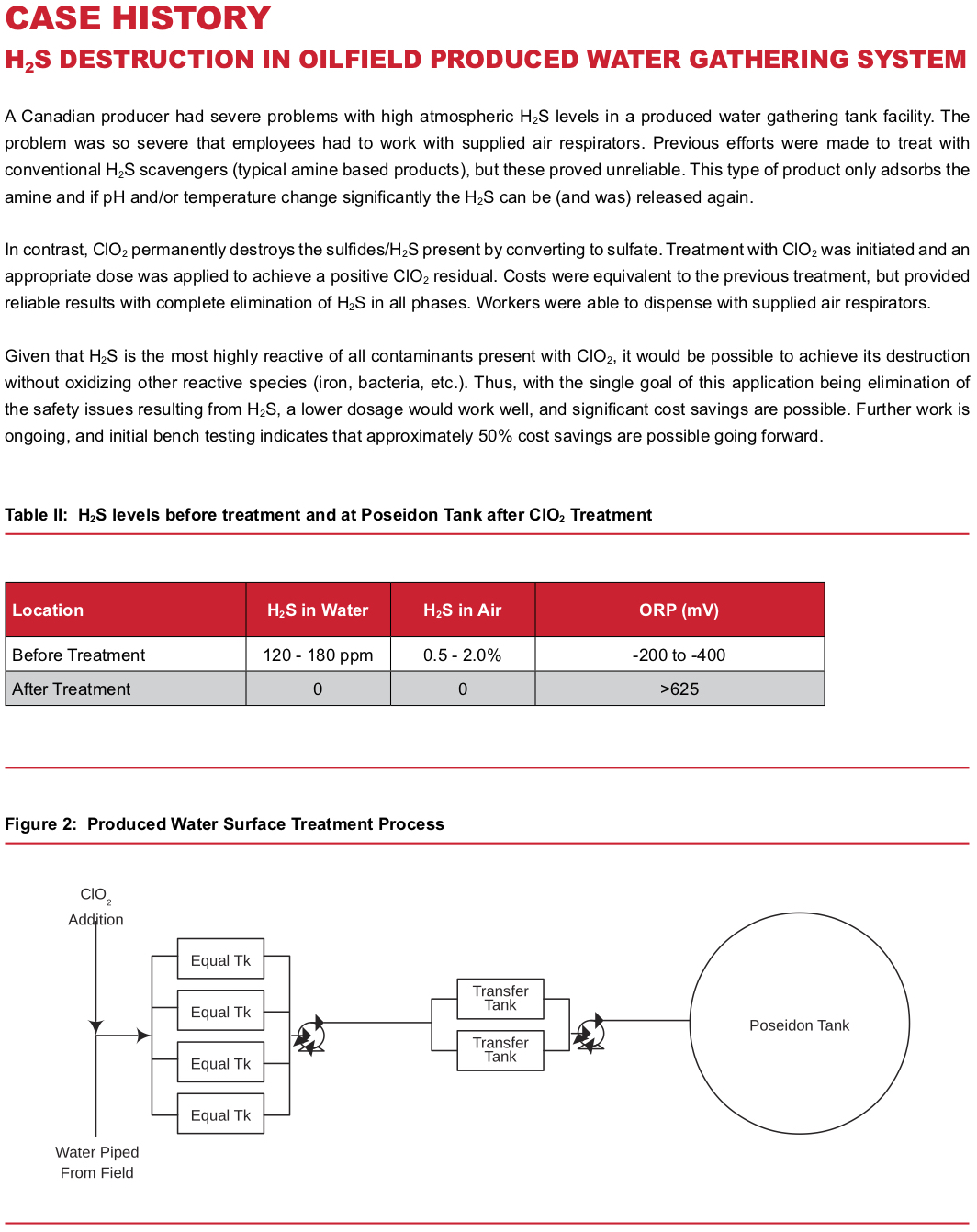
Chlorine dioxide oxidizes sulfide to sulfate in most cases, but there is some potential for formation of elemental sulfur. Multiple reaction pathways are possible and are highly dependent on pH and concentration. In any case, researchers have shown that, depending on conditions, it takes between 2.5 ppm and 4.5 ppm of ClO2 per ppm of sulfide present. Two of the possible reaction pathways are shown below. It should be noted that many alternative H2S scavengers are amine compounds, and with those products the H2S is adsorbed rather than converted to a different, harmless, molecule. These scavengers may release the H2S again if pH or temperature change significantly. Thus, they do not permanently eliminate the H2S hazard. With ClO2, H2S is rapidly oxidized and eliminated.
2e- transfer: 5H2S + 2ClO2 → 2HCl + 4H2O + 5S0(1)
8e- transfer: 5H2S + 8ClO2 + 4H2O → 5H2SO4 + 8HCl (2)
Iron Sulfide (FeS)
Iron sulfide serves to stabilize oil/water emulsions in many oilfield systems, particularly in tanks and pits handling produced water. It is also present in the biomass found in pipelines, well bores, etc. It may be dissolved with ClO2, with the general reaction equation shown below.
5FeS + 9ClO2 + 2H2O → 5Fe3+ + 5SO4-2 + 4H+ + 9Cl- (3)
The ferric ion formed reacts with water above a pH of 4.0 to produce ferric hydroxide Fe(OH)3 an insoluble floc. It can be easily removed by filtration. Common sock filters work well for this.
Now that we’ve shown how ClO2 resolves three of the core problems associated with oilfield production systems, the next step is to apply it to the various types of applications. The differences between the uses outlined below is simply which of the specific problems exist and where they are located. That is, how do we get the chlorine dioxide where it needs to be in the most efficient manner?
Hydraulic Fracturing
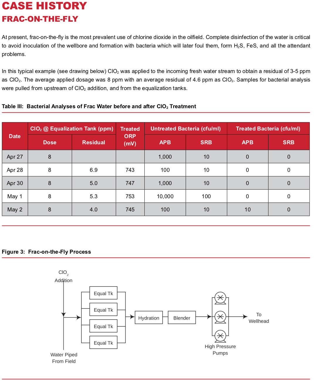
The primary goal of frac water treatment is to sterilize the fluids going downhole. Any live bacteria that are in the fluids will serve to inoculate the wellbore and formation. Over time, these bacteria colonies grow to plug formations, produce H2S (sour the wells) and FeS — ultimately producing all the problems discussed above. Therefore, if we can prevent bacterial colonization to start with, then the field will produce at higher rates, longer, with fewer problems.
Whether using fresh water, produced water, or a combination of both, the basic process is simple. Chlorine dioxide is injected into the water at some point in the water transfer lines upstream of the working frac tanks. The reaction with bacteria and other contaminants present is rapid, and a residual may be tested in the frac tanks to insure performance. A ClO2residual of 3-5 ppm is typically maintained in the frac tanks. See the attached case history for a typical system layout.
Produced Water
Produced water typically has significantly higher microbial populations than fresh water, and frequently has high H2S and FeS levels present. As would be expected, more ClO2 is required to treat these waters, as they contain more contaminants than fresh water. The key point, however, is that they can be, and are, successfully treated.
The order of reaction with the contaminants is H2S, then FeS, and finally, bacteria. Thus, it’s relatively easy to tell how the treatment is progressing by watching ORP (oxidation/reduction potential) and ClO2 residual. The presence of H2S produces a reducing environment, thus ORP is highly negative, being as low as -300mV in some cases. When ClO2 is added to the water, the ORP increases and H2S is rapidly destroyed. Longer reaction time is required to fully destroy FeS, which
is then followed by bacterial disinfection. By the time a stable chlorine dioxide residual is attained, all contaminants have been eliminated.
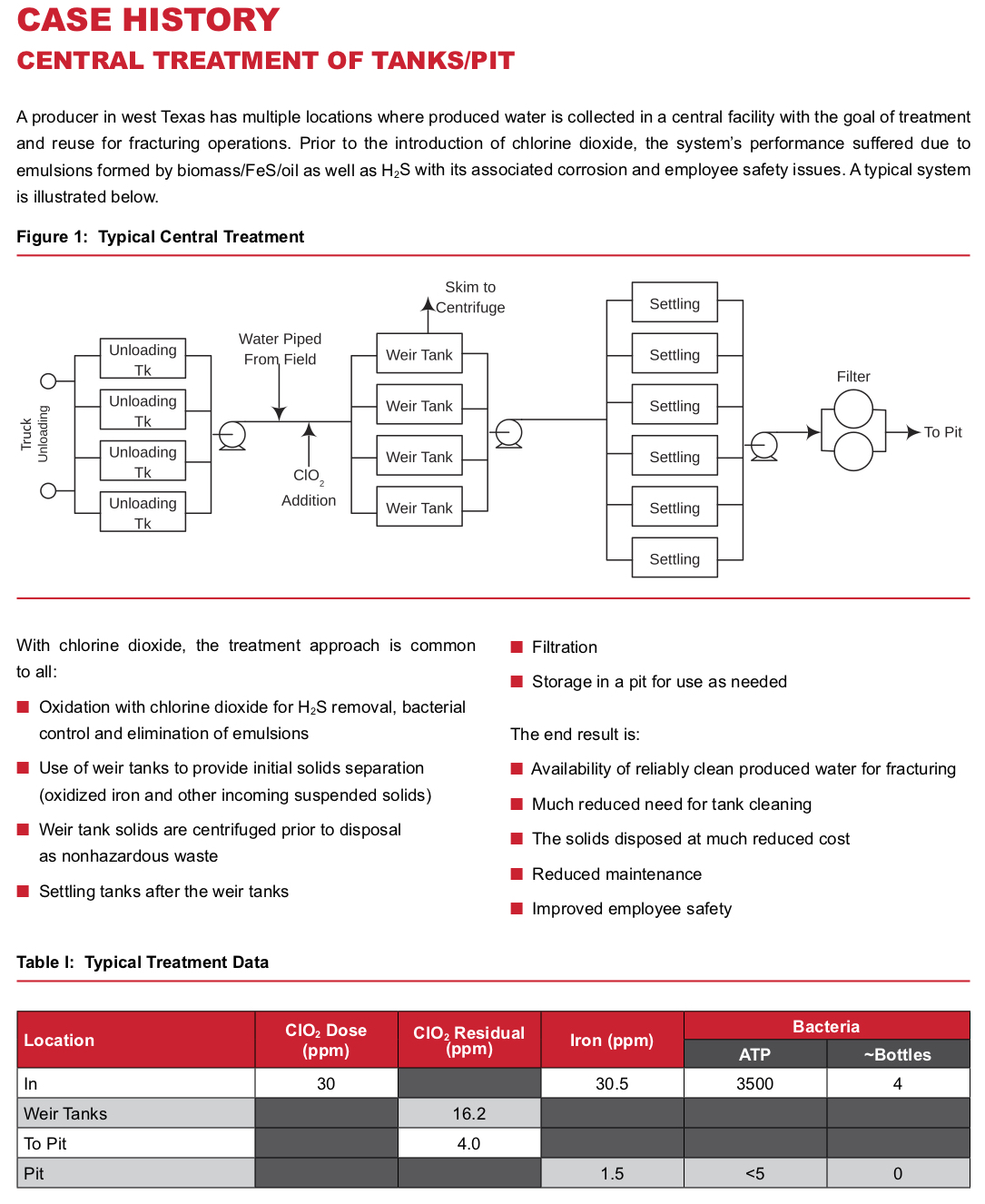
Produced water is used for numerous applications, from water flood injection, to frac water or simply disposal via injection well. In most cases handling it involves collection in a gathering tank system or pits initially. These tanks/pits have their own unique problems, which are discussed below. It is becoming common to treat the produced water and then put it into a pit for use as frac water, which also causes specific issues addressed below.
Gathering Tanks/Pits
Gathering tank systems and pits tend to have common issues. They serve to provide long residence time and allow oil to accumulate. This is an ideal environment for bacteria, allowing large amounts of biomass to grow and form a “rag” layer. This, in turn, provides an excellent medium for the growth of anaerobic, sulfate reducing bacteria and the resulting H2S. This, of course, further results in FeS formation due to corrosion. The combination of these factors forms a “rag”, or emulsion, that is extremely difficult to break.
The iron sulfide (FeS) acts to stabilize oil/water emulsions. When done in combination with the already existing biomass, most operators ultimately resort to draining and mechanically cleaning the tank/pit. This, of course, results in paying to dispose of hazardous waste. Thus, ClO2 is an extremely attractive alternative, since it will destroy the H2S, dissolve FeS and remove the biomass. The result is that the rag/emulsion layer in the pit or tank is resolved with much reduced need for solids disposal. In addition, the remaining solids can typically be disposed of as nonhazardous, for much lower cost. Routine low-level treatment (continuous or intermittent) of the system with ClO2 going forward prevents recurrence. Long term benefits of maintaining clean pits/tanks are clear — good quality water for injection or fracturing operations. And the treated water will not inoculate formations with bacteria to start the cycle again downhole.
Methods of treating tank systems vary. If individual tanks can be isolated, a good approach is to circulate a tank while maintaining a 25 ppm to 50 ppm residual of ClO2 in the water. This will provide for rapid breakup and elimination of the rag layer, typically requiring less than one day.
Alternatively, ClO2 may be fed upstream of the tanks and maintained at a low level (5 to 10 ppm) and gradually clean up the entire system. This method may require from a week to a month, depending on the amount of contaminants present.
Pits are treated similarly for cleaning. The difference is one of scale. They typically require a large pump (i.e., a 6\” or larger diesel trash pump) to circulate the pit, and chlorine dioxide is injected into the stream being recirculated. Special attention needs to be paid to insuring the sludge layer normally found on the bottom of pits is adequately treated. Best practice would be to put the circulating water discharge into or near the sludge layer and split the discharge line into multiple smaller ones.
Injection Wells (Water Flood or Salt Water Disposal)
In most respects, injection wells have issues very similar to tanks and pits. There is a continuously water wet environment with hydrocarbon present. Thus, you end up with the same problems with biomass, H2S, FeS and emulsions. Consequently, similar treatment approaches are effective. ClO2 will resolve them, with a few differences in approach. Either a stimulation, or “shock” treatment, or continuous treatment approach may be used.
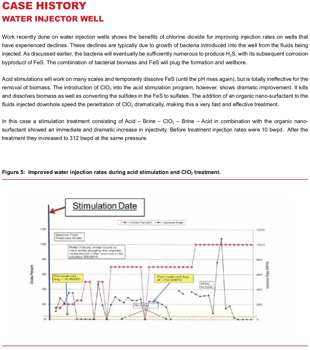
Stimulation Treatment — Due to temperature and solubility issues, there may also be scale formation in the well bore and near wellbore formation. While conventional acidizing treatment won’t be effective on biomass downhole, it is useful for scale removal prior to ClO2 treatment, allowing the ClO2 to more efficiently contact and react with FeS and biomass. So, an acidizing treatment is normally combined with use of a ClO2 slug (normally 100 to 200 barrels) for wellbore treatment. Results are rapid and dramatic, lasting from six months to several years between treatment.
Continuous Treatment — For a more gradual cleanup and maintenance approach, ClO2 may be applied to the injection water to maintain a 3-5 ppm residual. This maintains a clean system at all times.
Producing Well Stimulation
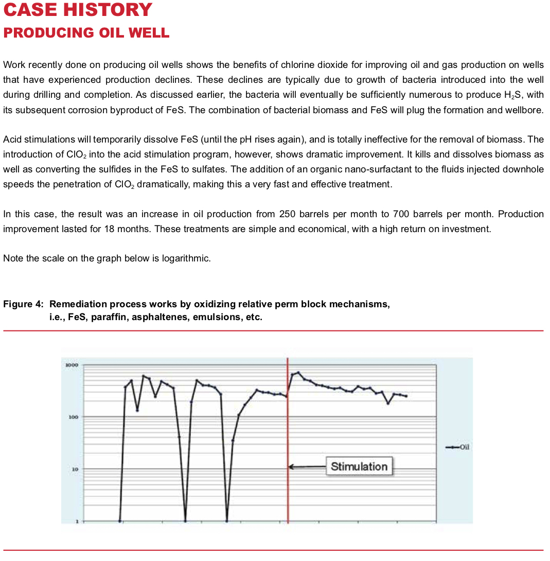
Producing wells, again, have similar issues to injection wells. Once contaminated with bacteria, usually during drilling and completion, biomass begins to grow and eventually produces the same cycle of H2S, FeS and formation pluggage. A stimulation treatment with acid and ClO2 will typically produce a major increase in well production, which is maintained for a long period of time. Production increases are frequently 3x to 5x the rate before treatment, often near or equal to original well production rates.
Polymer Floods
Polymer floods are relatively few in number, but they have unique issues. A polymer/water emulsion is injected into the field to sweep low API gravity oil from the formation to the producing wells. The produced fluid, therefore, is an emulsion of water, oil, and polymer. The challenge is to break the produced fluid and recover the oil from it. ClO2 in conjunction with a new nanofluid surfactant technology has proven extremely effective in breaking this emulsion. Commercial application is still developmental, but it shows great promise
Application Awareness
Safety
There are two primary aspects for safe chlorine dioxide application:
1. Storage and handling of precursors.
2. Safe concentration limits of chlorine dioxide in water.
As with virtually all chemicals, there are hazards, and well-established procedures exist for handling and storage. Chlorine dioxide is most commonly produced (as discussed in the next section) with sodium chlorite, sodium hypochlorite (bleach), and hydrochloric acid. Bleach and acid are already commonly used in oilfield operations, and operators already have procedures in place for handling them. The additional precursor involved here, sodium chlorite, has generally similar handling and storage requirements as sodium hypochlorite. However, it has one additional characteristic that must be addressed. If it is spilled and allowed to dry, it is a strong oxidizer and will typically cause a fire if it contacts organic materials (paper, wood, leather, hydrocarbons, etc.).
Common safe handling practices include:
- Provide proper containment, as with all chemicals.
- It is innocuous as a liquid, so do not allow it to dry.
- It is also easily neutralized with sodium sulfite.
- Contain oxidizers (chlorite and bleach) separately from acid.
Chlorine dioxide is a gas dissolved in water. As such, if there is a spill, it will evolve out of solution. A ClO2 concentration of 10% or more in air is flammable. Thus, properly designed ClO2 generation equipment will have a design that inherently limits product concentrations to levels that preclude the possibility of producing dangerous concentrations in the event of a spill. This is generally accepted in the industry to limit concentrations to 3,000 to 3,500 ppm exiting the generator.
Corrosion
A few companies have raised concerns about the potential impact of ClO2 on the frac equipment. Several recent studies have addressed this concern.
In one study, N80 carbon steel coupons exposed to 15% inhibited HCl for 5 minutes and subsequently to 50,000 ppm Sodium Chloride Brine with 1-5 ppm ClO2 for 1.5 hour, simulating a frac stage duration, showed no significant difference in corrosion rate from control samples without ClO2present. Corrosion was dominated by presence of inhibited HCl and brine.2
In another study, the corrosion rate of N80 steel coupons exposed to 7.5% HCl made from either deionized water or produced water each containing ~5 to 40 ppm ClO2 residual and 2.5 gpt corrosion inhibitor did not show statistically significant difference in corrosion rate from baseline comparison with no ClO2 present. Inhibited tests did show statistically significant difference from baseline uninhibited test.
ClO2 was shown to regenerate from residual chlorite ion in produced water used in making 7.5% HCl by dilution of more concentrated acid. However even these higher concentrations did not impact the corrosion rate of the inhibited acid. 3
In a third instrumented pilot scale study, which simulated actual conditions used in a slick water frac stage (velocity, temperature, duration, fluid additives, proppants, in fresh and in produced water, with and without ClO2 present) a variety of carbon and stainless steel alloys used in high pressure fracturing showed no statistically significant detrimental impact of maintaining 1 to 5 ppm ClO2 residual in the fluids.
However, the study showed the general corrosive, erosive nature of the frac operations. Corrosion rates were extremely high during the inhibited acid phase of each stage. Corrosion performance of carbon steel in fresh water started out poor.4Adding ClO2 had minimal impact. The presence of brine increased the corrosion rate by more than 30-40%. Corrosion increased with pH 5.8 or below and was reduced above pH 6. While it is known that O2 levels have significant impact on corrosion rate, the presence of ClO2 did not increase O2levels. Corrosion rate of stainless steel alloys was consistently good even with ClO2 present. Pitting was not detected over the course of this study.5
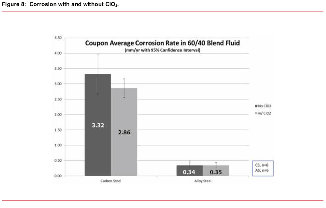
From these studies acidic solutions are the biggest contributor to corrosion in frac systems followed by salt from produced water. Frac iron systems just like salt water systems experience wet dry cycles that allow concentration of salts that significantly increase general corrosion and pitting.6 Proper use of inhibitors can minimize corrosion but not eliminate it.7 ClO2 when used at typical 1- 5 ppm residual concentrations for disinfection of frac water has minimal impact on the corrosive erosive nature of fracturing operations. See Figure 8.
Methods of Generating Chlorine Dioxide (Pros/Cons)
There are multiple reaction chemistries used to generate chlorine dioxide on the scale required for oilfield use. In general, they either oxidize sodium chlorite or reduce sodium chlorate. These methods have specific characteristics (safety, efficiency, cost) that strongly influence their suitability for our purposes.
Below are brief descriptions of the most common processes along with their pros and cons. In all cases the primary precursor (chlorite/chlorate) is in aqueous form, as are sodium hypochlorite (bleach) and acid (sulfuric/hydrochloric).
While it is not in the scope of this paper to address all the various ClO2 generators available on the market, there are two basic methods of feeding the chemicals into the generation process — pumps or vacuum eduction. It is the authors’ belief that the vacuum eduction process is much to be preferred for two reasons:
- Motive water flow through an eductor is used to create a vacuum that in turn pulls the precursor chemicals into the system to form ClO2. If motive water flow is lost, chemical flow stops and the reaction shuts down. Thus, it is inherently much safer than pump fed systems.
- Since chemicals are fed under vacuum, any leaks will draw air into the system rather than result in a pressurized leak of chemical to the outside environment.
Sodium Chlorite/Cl2 Gas (2-Part)
In this method, gaseous chlorine is educted into a water stream as shown by the first reaction equation below.
Cl2 + H2O → HOCl + HCl (4)
The hydrolyzed chlorine solution is then used to activate the chlorite ion as shown in the following equation.
2NaClO2 + HOCl + HCl → 2ClO2 + 2NaCl + H2O (5)
This process is the most economical method to produce ClO2 from sodium chlorite, as well as being very simple. There is, however, one major drawback to this process that prevents its use. It requires the use of one-ton chlorine cylinders to transport the Cl2 gas precursor. Any leaking chlorine cylinder can potentially expose many square miles of country to lethal concentrations of chlorine. This is the same reason that most industrial facilities have discontinued the use of chlorine gas.
Sodium Chlorite/Bleach/Acid (3-Part)
This reaction chemistry is similar to that shown above, except that the hydrochloric acid and bleach are fed as separate liquid precursors.
2NaClO2 + NaOCl + 2HCl → 2ClO2 + 3NaCl (6)
This is the most efficient, safest, and economical reaction chemistry available for use in all oilfield applications. With properly designed equipment, reaction efficiency is typically 98+% and precursors are readily available from numerous sources.
Sodium Chlorite/Acid (AC)
In this process, chlorite is acidified to produce chlorous acid which disproportionates to produce chlorine dioxide. While researchers state that several reaction pathways can occur in this reaction, the general equation is as follows:
5NaClO2 + 4HCl → 4ClO2 + 5NaCl + 2H2O (7)
While this reaction is used relatively commonly, it does have several serious drawbacks, such as
- Poor yield, thus higher cost. Note that only 80% of the sodium chlorite is converted to ClO2 (4 moles of ClO2 are produced from 5 moles of NaClO2).
- To achieve reasonable reaction efficiency and speed, acid must be overfed significantly versus stoichiometry to achieve a pH of <0.5. This typically requires an acid overfeed of 3x to 5x. This adds further cost as well as corrosion concerns.
- Precursors are reacted in concentrated form, thus resulting in ClO2 concentrations of well over 100,000 ppm in the generator. Refer to safety discussion above.
Some vendors have also claimed that the cost inefficiencies are not real, since the “unconverted chlorite” is in fact still available in the water and is pumped downhole (assuming it is being used for fracturing operations) and will convert to ClO2 in the acidic environment that exists there. This claim is patently false, for as the reaction demonstrates, any unconverted chlorite will still be subject to the reaction stoichiometry in Equation (7) if and when it is activated downhole or, more likely, will be consumed in other reactions.
Sodium Chlorate
This generation chemistry has been used for many years for large volume applications such as pulp and paper bleaching. Small scale generators were developed relatively recently that are suitable for oilfield use. Sodium chlorate is reacted with hydrogen peroxide and sulfuric acid. The ratio of chlorate to peroxide is fixed, so these two precursors are combined into one product. Thus, the three chemistries are available in the form of two precursor products. Several sources of these chemistries are now available.
2NaClO3 + H2O2 + H2SO4 → 2ClO2 + O2 + Na2SO4 + 2H2O (8)
Chlorate chemistry has the advantage of being economical. Sodium chlorate is produced as an interim step in the production of sodium chlorite; thus, it is less expensive as a precursor. However, the reaction chemistry causes a couple of concerns.
The reaction requires high purity sulfuric acid of 78% concentration. If the acid is not sufficiently pure (less than approximately 50 ppm iron content), the reaction may be inefficient or the reaction chamber suffer damage due to micro-“puffs”. The generator must then be flushed/cleaned of the contaminated acid, repaired if necessary, and a clean acid supply provided. Thus, the purity of the acid supply and its handling is of high importance.
The sulfate present in the solution from the sulfuric acid can be problematic in many oilfield waters. If even low levels of barium or strontium are present, they will form an insoluble precipitate with the sulfate and scale equipment and downhole formations.
Precursors are reacted in concentrated form, thus resulting in ClO2 concentrations of well over 100,000 ppm in the generator. Refer to safety discussion above
Conclusion
While no chemical is a panacea for all problems, chlorine dioxide does have a unique ability to solve several of the core problems universally encountered in the oilfield environment. H2S, corrosion and emulsions are in most cases traceable back to microbiological growth. Chlorine dioxide, as an oxidizing chemistry, kills all forms of bacteria and eliminates H2S. The elimination of H2S then greatly reduces system corrosion and the resulting FeS that aids in stabilizing emulsions. Where FeS does exist, ClO2 dissolves it, generally resolving the emulsion and any blockage that is present. At the same time, ClO2 is weak enough that it does not react with hydrocarbons and most other organics, unlike stronger oxidants like bleach, ozone, peroxide, etc. Finally, it has an easily testable residual which allows precise dosage control.
Taken all together, chlorine dioxide provides the ability to solve several key problems with one flexible chemistry. As the discussion of ClO2 production methods indicates, the 3-part chlorite/bleach/acid generation method is preferred to other options for oilfield operations. When combined with generation equipment that utilizes vacuum eduction for chemical feed, it optimizes cost, safety, and performance
